Assembly Method
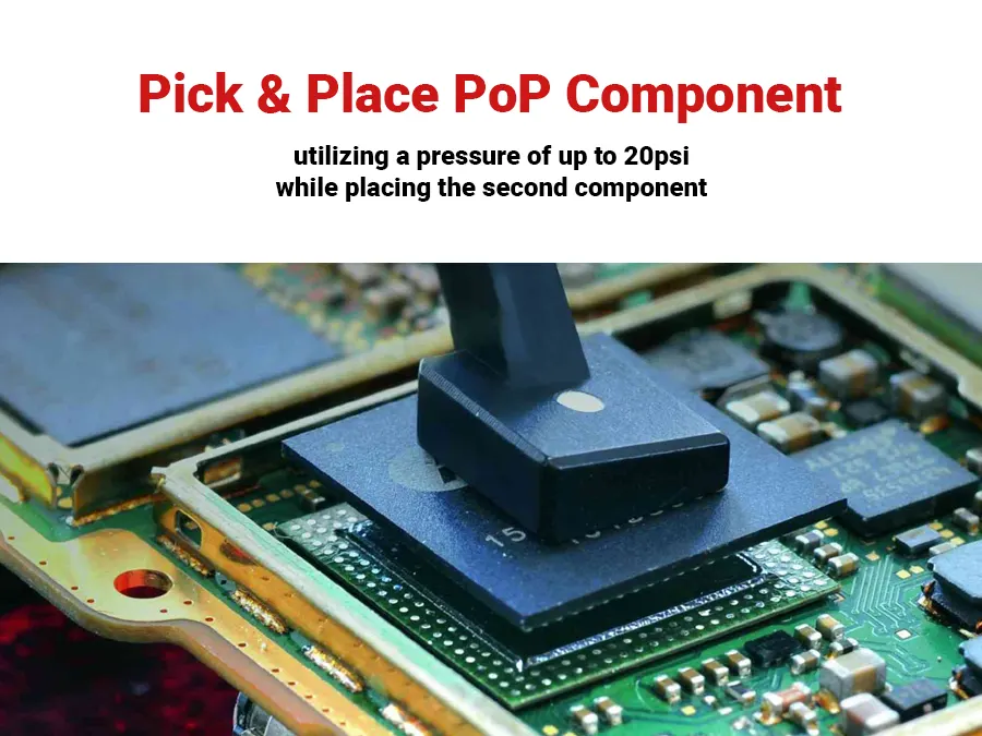
There are two primary techniques for PoP assembly: pre-joined and on-the-fly. The key distinction between these methods is the assembly process, not the final outcomes. The pre-joined approach employs a two-pass process in which the devices that will be stacked later are assembled in the first pass, similar to standard SMT assembly. Components are placed onto other devices in a carrier, and the entire carrier is sent through reflow to join these parts. The now pre-joined devices are then re-packaged for picking by the assembly system (normally tray) and returned to the placement machine for stacking or placement on top of another device. In some cases, one layer is added at a time, and the stack goes to reflow after each layer, while in others, the entire stack is assembled before going through reflow.

Pre-joint Assembly
There are two primary techniques for PoP assembly: pre-joined and on-the-fly. The key distinction between these methods is the assembly process, not the final outcomes. The pre-joined approach employs a two-pass process in which the devices that will be stacked later are assembled in the first pass, similar to standard SMT assembly. Components are placed onto other devices in a carrier, and the entire carrier is sent through reflow to join these parts. The now pre-joined devices are then re-packaged for picking by the assembly system (normally tray) and returned to the placement machine for stacking or placement on top of another device. In some cases, one layer is added at a time, and the stack goes to reflow after each layer, while in others, the entire stack is assembled before going through reflow.

On-the-fly assembly
When it comes to PoP assembly, the pre-joined method offers a simpler process for the placement machine, resembling traditional SMT assembly. However, it does come with additional handling and potential issues to keep in mind. For instance, subjecting a component to multiple reflow cycles can lead to heat stress and oxidization or crystallization of solder joints lacking flux. Therefore, it’s important to consider these factors when deciding on an assembly method.
Fluxing
The most significant difference in the assembly process of PoP is the need to apply flux to components. In typical SMT assembly, solder paste is used with a stencil printer on the PCB, and components are placed on it.
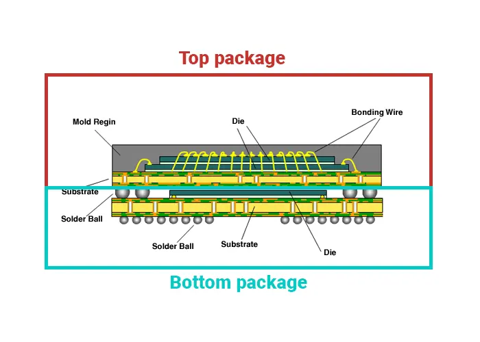
However, this method is insufficient for PoP due to the stacked parts. In PoP assembly, the first layer of parts is placed on the PCB, and subsequent layers are placed directly on top of it. Although it is possible to print solder paste onto the PCB for layer one placements, there is currently no method to apply solder paste to the tops of these parts after they have been placed.
When assembling PoP, it is recommended to use either flux or dippable solder paste on the balls of layer 2 and higher parts. This step must be performed during the assembly process as the parts are transferred directly from their packaging (tape, tray, etc.) to the PCB. This paper solely focuses on the assembly process of PoP and does not delve into the advantages of using flux or dippable solder paste. The only distinguishing factor between these two options, from an assembly perspective, is their effectiveness in the flux unit.
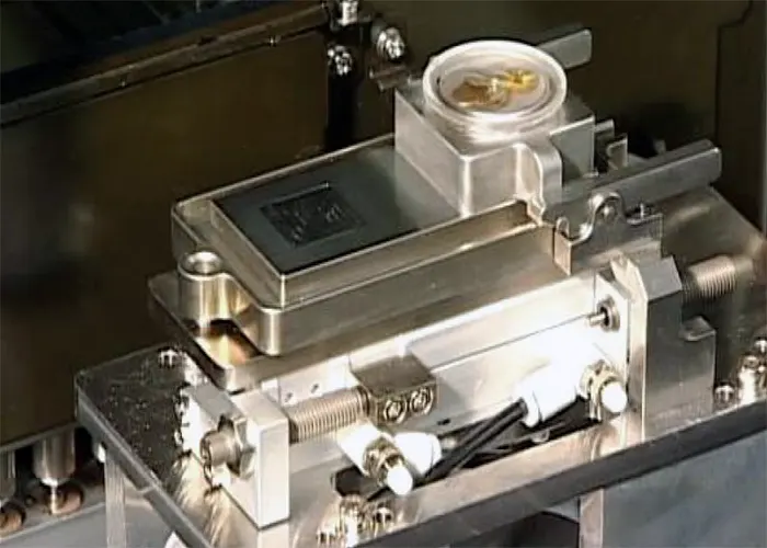
Fluxing has been around for many years on different machines on the typical SMT floor but has rarely been used on mainstream SMT assembly systems. Specialty placement machines designed more for semiconductor placement have also used fluxers for many years. There are two main types of fluxers used for SMT assembly systems: linear and rotary. The main task of the fluxer is to provide a method of applying a uniform and consistent amount of flux to the components.


Flux/Solder Paste Dip
When it comes to PoP assembly, flux or solder paste dipping can be a suitable option if there is only one component on each layer or a total of two layers. This approach minimizes the need for extensive processing and handling of devices. However, it does add processing time for each placement due to the component dipping process, which is in addition to the normal pick center place time. Therefore, it may not be the most practical choice for devices with more than one component per layer. Nonetheless, compared to traditional SMT assembly, the flux dip method involves only two extra steps.


